ESP32 pinout: which GPIO pins to use, and which to avoid
You wired a sensor, uploaded the sketch, and nothing works. Or the board refuses to boot with a wire attached. In many cases the cause is the same: you picked a pin that has a special job. The ESP32 is flexible, but not every GPIO is equal.
This guide shows which pins to use first, which ones need care, and which to leave alone.
The short answer
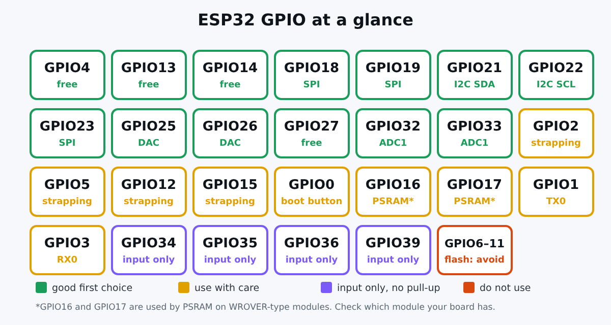
For a first project on a classic ESP32 DevKit, these pins are good choices: GPIO4, 13, 14, 18, 19, 21, 22, 23, 25, 26, 27, 32 and 33. They have no boot role and are not connected to the flash.
By convention, GPIO21 is I2C SDA and GPIO22 is I2C SCL in the Arduino core, which suits most I2C sensors.
Pins to leave alone: GPIO6 to GPIO11
On the classic ESP32, GPIO6 to GPIO11 are connected to the internal flash. Espressif's FAQ says that on the WROOM-32 family these pins are occupied by the flash and cannot be used for other purposes (Espressif GPIO FAQ). Many boards do not even break them out. If yours does, ignore them.
Input-only pins: GPIO34, 35, 36 and 39
GPIO34 to GPIO39 can only be inputs, and they have no software-enabled pull-up or pull-down resistors (ESP-IDF GPIO reference). They are perfect for analog sensors and buttons with an external resistor. You cannot drive an LED or a relay from them.
Strapping pins: GPIO0, 2, 5, 12 and 15
Strapping pins are read by the chip at boot to decide how to start. ESP-IDF lists GPIO0, GPIO2, GPIO5, GPIO12 and GPIO15 as strapping pins on the classic ESP32 (ESP-IDF GPIO reference). If an external circuit pulls one of them to the wrong level during boot, the board may not start, or may not enter upload mode.
- GPIO0 is tied to the BOOT button: held low at reset, it puts the board in upload mode.
- GPIO2 often drives the on-board LED on DevKit boards.
- GPIO12 is a classic trap: a pulled-up wire can make the board refuse to boot.
You can use them after boot, but keep sensors and relays with strong pull resistors away from them.
ADC2 and Wi-Fi do not mix
The ESP32 has two analog-to-digital converters. The ESP-IDF documentation notes that ADC2 pins cannot be used when Wi-Fi is used (ESP-IDF GPIO reference). Pins such as GPIO4, 12 to 15, 25 to 27 are ADC2. For analog readings in a Wi-Fi project, use ADC1 pins: GPIO32 to GPIO39.
TX and RX
GPIO1 (TX0) and GPIO3 (RX0) carry the serial logs and are used for flashing through the USB chip. Do not use them for other things unless you give up serial output.
GPIO16 and GPIO17
On modules with PSRAM (WROVER type), GPIO16 and GPIO17 are connected to it. ESP-IDF says they are usually connected to flash or PSRAM on the module and should not be used otherwise. On boards without PSRAM they are free, so check which module is on your board.
What changes on the ESP32-S3
The ESP32-S3 has more pins and different rules:
- On boards with octal PSRAM, like the N16R8, GPIO35, 36 and 37 are used internally and unavailable. Our N16R8 guide explains why.
- Strapping pins include GPIO0, GPIO3, GPIO45 and GPIO46; check the datasheet of your exact module before using them.
- USB runs on dedicated pins (GPIO19 and GPIO20), so avoid them if you use native USB.
- Any signal can be routed to almost any pin through the GPIO matrix, so there is more freedom than on the classic ESP32.
You can see the pins of both boards in the shop: ESP32 DevKit and ESP32-S3 N16R8 DevKit.
A quick checklist before you wire
- Is the pin one of GPIO6 to 11? Do not use it.
- Do you need an output? Do not pick GPIO34 to 39.
- Do you read analog values with Wi-Fi on? Use ADC1.
- Is it a strapping pin? Make sure nothing pulls it at boot.
- Is it TX or RX? Keep it free for logs.
- On an S3 with octal PSRAM, is it GPIO35 to 37? Pick another.
Example: a DHT22 on GPIO4
Our DHT22 tutorial uses GPIO4 because it has no boot role and is not connected to the flash. That is the kind of pin to look for.
Conclusion
Most "my ESP32 does not boot" stories come from a strapping pin, and most "my ADC reads zero" stories come from ADC2 with Wi-Fi. Stick to the green pins on the chart, and your first projects will just work.